
|
Build Blog Last updated 5-11-2015 **** May take some time to load due to many pictures- Please wait***** |
Page 4
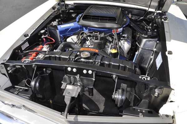
January 11, 2015: Aircleaner & Airpan
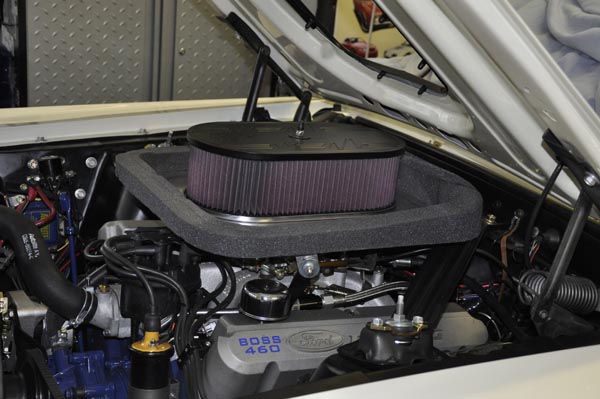
Early on in the build I modified a shaker to fit under the hood which required squeezing things together and as a result reducing air flow with a filter element of 13" diameter and just about 1.75" tall. It is perfectly fine for normal driving, but at the track it restricts airflow too much and killed my top end. I did a quick test with a much larger 9x12x5" oval cleaner that stuck through the hood, and so much better gaining 3 mph.
Also went through some of the typical calculations for aircleaner size (K&N, web site and others), and calculated surface area value about 2.5x my shaker element. I will have the car on the chassis dyno in the spring and will do some comparisons there with and without, as well as the track to get better data.
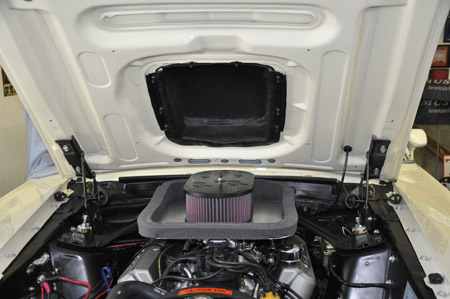
Rather then just sticking the aircleaner on and having it open to the engine bay heat, I decided to fab an airpan that would seal it to the underside of the hood.
This K&N Aircleaner flows much better that the shaker one and is the largest one that I found that would fit well in the hood hole.
The airpan was made out of 1/8" aluminum to be rigid, yet as light as possible. The center section is a K&N 66-1560 aluminum base that was modified and bolted to the flat pan. This base provides a rigid surface for the aircleaner element to properly seal. It turns out that this assembly is about .5lbs less than the shaker assembly. I did not like the polished top, so I bead blasted it and then put a semi flat paint on it it.
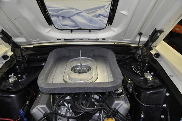
The foam is made for airpans, and is glued using high performance weather-strip adhesive, and has been cut and contoured to follow the underside of the hood profile for good sealing without too much pressure when the hood is closed..
To minimize stress on the aircleaner stud in the center of the carburetor, the airpan has a tab that attached to the stock shaker bracket. That supports the pan just like the shaker assembly is supported.

Lastly to minimize head, the underside of the pan has been covered in a reflective heat barrier by Design Engineering. The insulator wraps around the pan edges and stops under the foam for a nice clean look.
To mount it to my air pan, on the bottom pan of the AC assembly, I drilled
6 holes in the base and countersunk them, so the element bottom is on them.
The 6 SS countersunk screws attach to the pan with washers and nylock nuts.

The next step will be to fab a scoop that can easily attach to the hood using the shaker trim ring studs for easy swapping. Again, I am hoping to make something with a similar stock look if at all possible, and still be able to swap between shaker assembly and this within 5 minutes.
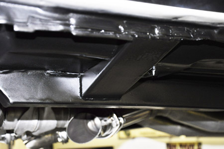
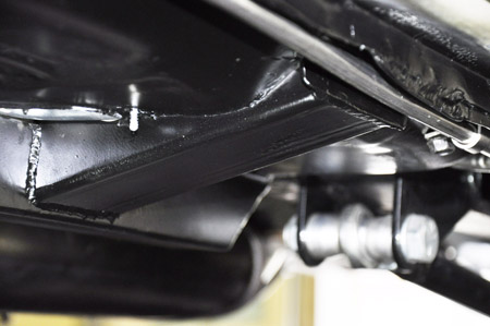
January 25, 2015: Exhaust Cutouts
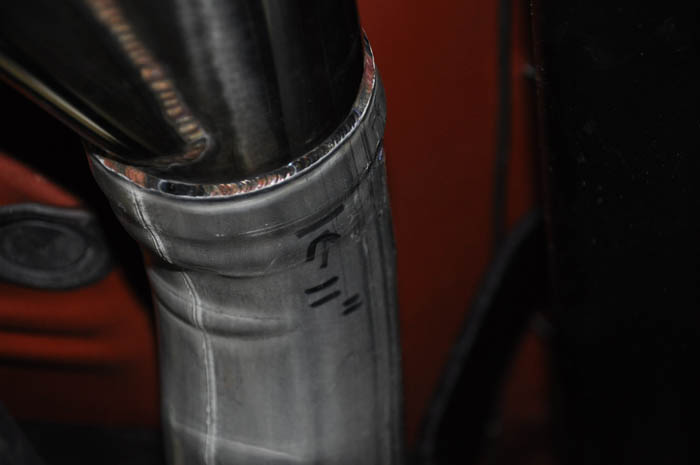
There is always something to do on my list for this car. When doing the exhaust last year I was going to put in electric cutouts, but with the 3" pipe, driveshaft loop and other stuff under there, they would of been to low to the ground. The nice electric units, such as Dougs, are big. That was not a big deal since the local track previously did not allow open exhaust on street nights. Last year they became much more flexible and if there was bracket racing going on, allowed open exhaust. This winter I am doing a few misc things on the car and I decided to add some cutouts that I can manually bolt on block plates or turndowns. It was still a tight fit and not may areas along the pipes I could locate these.
TIG welded the cutouts to the existing pipes after using an expansion die. Decided to locate them further back where I could have more ground clearance, plus direct sound away from under me. Also tacked the nuts to the back side of the flange so I can easily unbolt or bolt the caps in place with one hand, and also tacked the turndowns to their flange so they will always be in the right direction.
The list goes on.

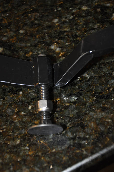
January 28, 2015: Clutch Pedal Stop
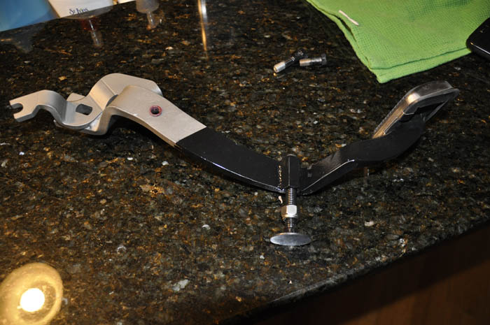
To control how far the clutch pedal gets depressed helping with over-travel past the point of clutch disengagement and provide more consistent shifts, I added an adjustable clutch stop to the pedal.
TIG welded a 3/8"-16 coupling nut to the clutch pedal. An elevator bolt with a large flat end was used along with a jam nut to hold the adjustment. The coupling nut is at a slight angle to the pedal bar so when the clutch pedal is depressed, the flat surface of the elevator bolt hits the firewall flat in an area near the steering column where it is very solid. Once I get this adjusted, I will probably have to cut the bolt down so the threaded section does not stick past the pedal bar. What is not shown in the picture is a dense 1/16" thick piece of rubber glued to the flat of the bolt.
February 13, 2015: Adding a 2-Step Rev limiter and Neutral Safety Switch
To help with more consistent launches a 2-step rev limiter was added. This will help with controlling and having consistent launch RPM. It is also tied to the line loc so the launch rev limiter is disabled when the clutch pedal is released. For staging, the way it is wired is when the clutch pedal is depressed AND the line loc button on the shifter is pressed, a latching relay is engaged holding the 2-step and line loc engaged. At that point the line loc button on the shifter can be released and until the clutch is released (pre-set clutch pedal height) the 2-step and if selected line loc stay engaged. From then on, when shifting to 2nd, 3rd, and 4th, the 2-step is never engaged again, and only the primary rev limiter on the MSD box is active. For bunouts, the 2-step is disabled, and the line loc functions normally off of the shifter switch.
I selected an Omron D4C-1620 limit switch because of being highly reliable, can withstand excessive vibrations, as well as having a completely adjustable pivot arm making it easy to adjust the point at which the switch closes and opens, thus setting when clutch pedal releases the 2-step and line loc.
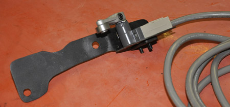
The bracket is fabbed out if 1/8" aluminum and mounts using the 2 steering column bolts that hold the column through the firewall. The bracket also allows for vertical adjustment of the switch to further refine the switch release point.
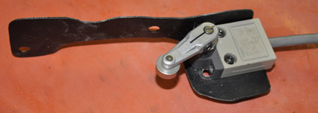
With the hydraulic clutch assembly there was limited room to fit this in and have it align correctly, so there were a few cardboard mockups. The switch pivot arm has a roller on the end that lines up with the clutch pedal and rides along the back of the pedal bar. The arm can be positioned so the switch opens based upon clutch pedal height, and thus, clutch engagement.

The 1970 Mustang 4-speed did not come with a neutral safety switch, and the local track rules state that if the car did NOT come with one, and has a STOCK Manual transmission one is not required (is required for automatics, no exceptions). I have a TKO-600, so it could be a sticking point with "some" tech inspectors. Given that I have this clutch pedal switch now there, it was an easy addition to add a neutral safety switch. At the firewall there is a plug that the reverse light harness from the transmission connects to, and for a manual transmission, there is a wire loop to bypass the automatic transmission neutral safety switch. I took advantage of that by breaking the loop and adding a relay. I do have a "secret" bypass switch just in case the relay fails, I do not want to be dead in the water.
This small relay board is mounted on the floor under the dash and tucked under the console. The larger relay is a Double Throw- Double Pole, that is activated off of that clutch switch. Half of the relay is used for the neutral safety switch to make/break the "loop", and the other half is used in conjunction with the smaller relay to create a latching circuit for the rev limiter and line loc.
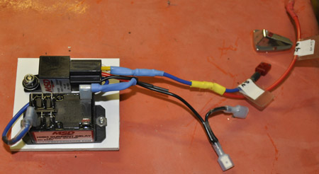
There is also some flexibility built in. The line loc can be used alone without the 2-step such as for burnouts, and also the entire 2-step can be disabled. The two rocker switches in the console control what is enabled and a momentary push button on the shifter is used for the line loc and the clutch pedal switch for the 2-step.
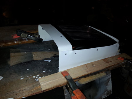
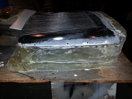
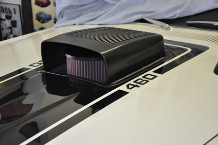
March 1, 2015: Custom Shaker looking scoop for airpan
I did not like the look of the air pan aircleaner sticking through the hood, and did not want to permanently mount a scoop since I wanted to be able to convert back to the Original Shaker Style system, so I created a shaker look alike scoop that could easily be mounted to the hood. The Shaker top could not be mounted directly to the air pan since the added height to clear the aircleaner would not allow for enough hood clearance during opening and closing, so it needed to be attached to the hood.
Starting with a fiberglas top from Ford Ram Air, I cut the base off so it was just the top lid section.
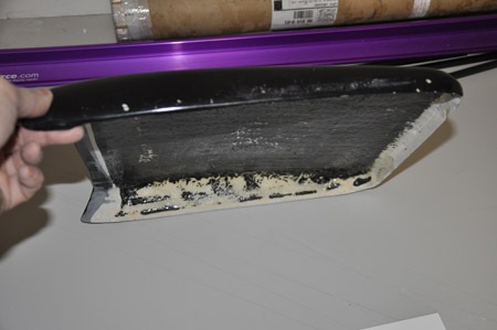
Then I needed to fab a mold to lay the Fiberglas in. I used 3mm sintra which is a rigid, yet easy to shape plastic material. Sections were screwed into the shaker top. When the sintra is heated with a heat gun, it can be bent and will hold the shape. The other reason for using sintra is it is very smooth (like Teflon) and the fiberglas resin would not stick to it. The mold sides were screwed into the lid with self taping screws after pilot holes were drilled
Once the sides were attached, I needed to determine the exact height and angle of the shaker top so it would clear the aircleaner lid, and follow the hood slope. The assembly was shimmed to get the correct height and angle then it was marked along the outside edge where it would meet the hood underside for the mounting flange.

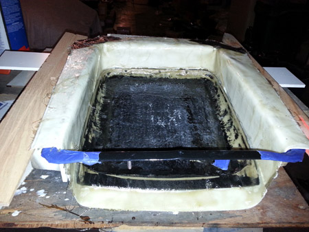
Using the hood shaker trim ring, and some spacers around the sides and back to provide a gap between the scoop and the ring, I started to form the rest of the mold. The mold pieces were screwed right into the shaker top. The sintra could be heated with a heat gun and then shaped. Note that the top was made both higher, slightly wider and longer to fill the entire hood opening with just enough clearance for fitment.
Next step was to create the flange mounting surface and get a nice transition edge between the vertical sides and the mounting flanges. The bend had a small radius that the fiberglas matting would follow.

Once the flanges were roughly shaped the scoop was clamped down to a sheet of plywood and a heat gun heated the sintra from the inside along the bend. This ensured that the sides and back were all flat and even.
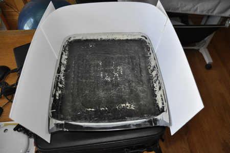
To maintain the outside dimensions during laying the fiberglas, the hood trim ring was held in place along the flange area along with 1/4" spacers. This would hold the right shape and required clearances as the first of 4 layers of fiberglas was laid down.
After 2 layers of fiberglas was laid down, the mold was removed.
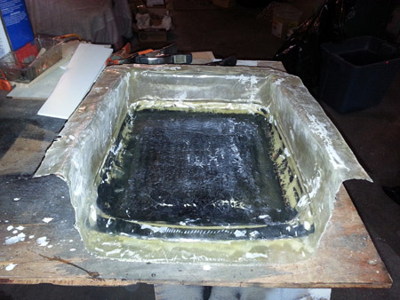
A final test fit was done before any additional fiberglas was laid down.
Even though the fiberglas cloth was attached to the underside of the lid, to make sure there is no separation of the top, a series of holes were drilled into the top section and fiberglas strands were fed through the holes and onto the fresh fiberglas sides on both the inside and outside. Another layer of fiberglas was laid along the outside and along the inside encapsulating the fiberglas reinforcements and adding stiffness to the assembly. A good coating of resin was applied over this final surface.
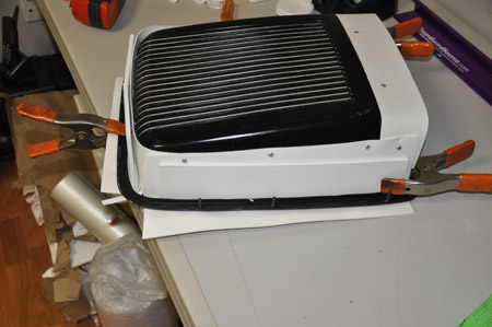
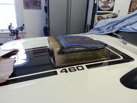
After rough sanding of the fiberglas, a skim coat of bondo, more sanding, some high build primer and even boarding, the surface was ready for paint. A semi flat paint was applied and then the silver accents along the top were added. To help with sealing it to the hood and reduce vibrations, an adhesive strip of foam was put around the edge on top of the flange. This would get sandwiched between the underside of the hood and the scoop.
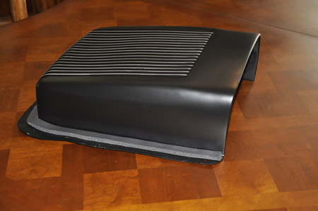

In less than 10 minutes the car can be back to its original looking configuration with the shaker aircleaner.
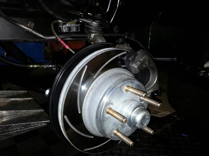
March 16, 2015: Longer Wheel Studs
If you are using the Stainless Steel Brakes Drum to Disc conversion Kit A134 or any of the kits that use the SSB A236 hub assembly and want to install longer wheel studs this will save you time in your stud search. With my front skinnies mounted on drag light wheels, the thicker center section of the wheels resulted in the minimum amount of stud/lug nut engagement which I do not like. After lots of searching for longer wheel studs (including talking with SSB), the "only ones" I could find that had the proper knurl, as well as base length were these from ARP. The issue was not just the knurl size, since I could of drilled the holes larger, but once you get beyond the standard length, finding the correct profile (length of knurl and location) so it properly engages with the 2-piece assembly limits you.
Here is a comparison of the one that comes in the hub versus the ARP 100-7707 ones. It is a perfect fit. As a side note the ARP ones are Gold since their price is like gold at $16/bolt :)

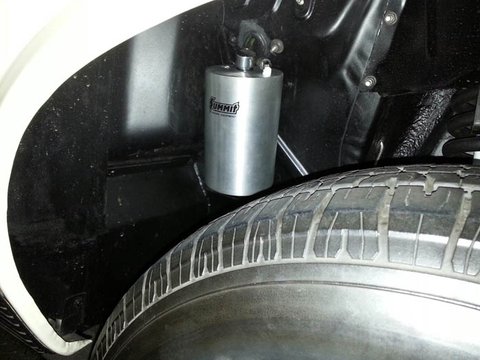
March 18, 2015: Vacuum Canister
The vacuum on the Boss 460 is around 13inHG at 800rpms (idle) and quickly jumps up above 1500rpms to 25inHG. The 13 works fine and stops the car with no problems, but you do need to push hard to completely "lock up" the front tires especially when doing a burnout prior to staging and using the line loc. I decided to add a vacuum can to take advantage of the higher RPM vacuum. The can is in the general stock location for the AC vacuum can inside the right wheel well. With a quick blip of the throttle before staging, the can holds enough vacuum for 6+ brakings with moderate pressure so I do not have to think about pushing the pedal super hard at staging.
April 26, 2015: Roll Bar and other safety stuff
With the car last year just being over 11.5 sec in 1/4 mile with granny shifting it, I was on the edge of needing a roll bar. With the transmission modifications, 2-step added, clutch switch and other mods done this past winter I am hoping to be in the low 11 sec range. With that comes more safety, so I had a custom chromoly roll bar installed by DMC Racing here in Massachusetts. They did an excellent job of keeping it very tight to the inside, yet not so tight that I can't remove interior panels, and completed the job when they said.
The worst part of this install was painting the roll bar. Basically had to mask off the entire car except for the bars since I wanted to spray it. It was tight but was able to get complete around the bars with a small spray nozzle. Epoxy primer was followed by a satin black chassis paint. Then to better match the interior, I dusted everything with charcoal black metallic paint normally used on the interior panels.
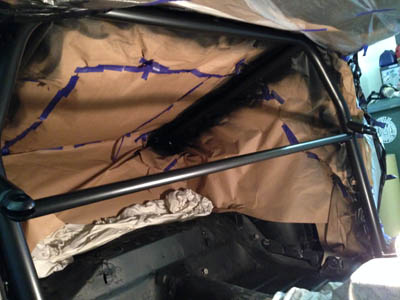
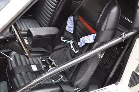
Both the driver and passenger side has swing outs and with the pull of a lower pin, can be completely removed. This pic is with the stock seats, however, the plan is to stick in Kirkey seats at the track. Also went with a Stroud 5-point camlock harness so I do not need to fumble trying to get all the belts into a latch.

You can't really see it in this picture, but the stock seatbelts are still in place. With the roll bar being so tight, I did have to fab an extender bracket to allow mounting the upper seat belt point.

The mail hoop is covered with BSCI SFI 45.1 padding.. The padding comes in 36" lengths and is very stiff, so it needed to be heated with a hair dryer and slowly formed so it would not crack. I used clamps and zip ties to form it to the hoop as it was heated. IN the end fit perfectly with no cracks..
The padding also has an 2-sided tape on the backside, so once it was formed, the tape was exposed and pressed in place. I also used Velcro straps to keep in in place
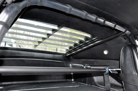
The rear hoop supports follow the roof line and go right into the trunk. This allowed me to keep the fold down seat with no modifications at all.
The door bars are a very tight fit. A slight inward bend (3/8") gets it around the door handle.
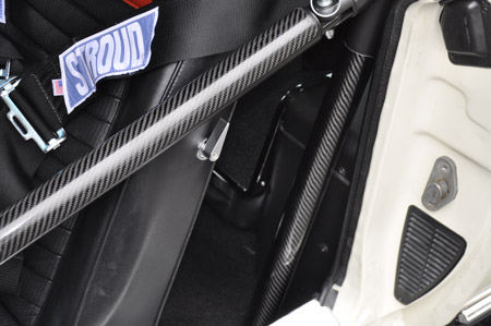
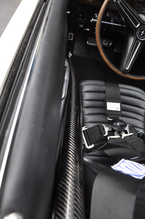
The top surface of the door bar, and front of the lower main hoop bars have carbon fiber, tube protectors glued on. I figured those two areas would get all chipped up from getting in and out and putting stuff in back. The carbon fiber is a good match to the stock interior panels.
To stiffen things up even more, since I already had welded in subframe connectors, had DMC also add add an outrigger between the rockers and the subframe connectors. These 2.5"x4" chromoly outriggers go through the floor, welded to the floorpan, and then the main hoop welded to them.
The only modification that I made after I got the car back was to put a channel on the left side for the fuel line to stay in the original place. A slot was cut and u-channel piece of 1/4" CM was welded in to keep the fuel line recessed as OEM. There was also another piece if CM welded between the rocker and outrigger above the u-channel for added support.

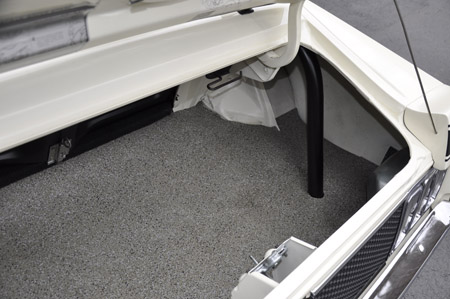
Since the OEM trimmed mats only cover about 3/4 of the trunk due to the spare on the right side, I picked up OEM spatter burtex sheet stock from ACC and made my own to cover the entire floor.
Next on the list is to finish the Racepak data logger install.
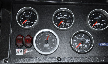
May 11, 2015: Racepak Sportsman Install
I have always wanted the ability to log various things, so I decided to install a Racepak Sportsman data logger. The logger allows me to record sensor data for review later, or connect my laptop to it for a real time telemetry session create graphs.
The Racepak unit has both an Acceleration G meter, as well as a lateral G meter built in. Given that it needed to be securely attached to the car. They recommend not attaching it to the floor due to vibrations, so I opted to attach it to the lower part of the side roll bar. I fabbed a bracket out of 1/4" aluminum so it is rigid.
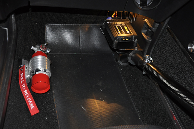
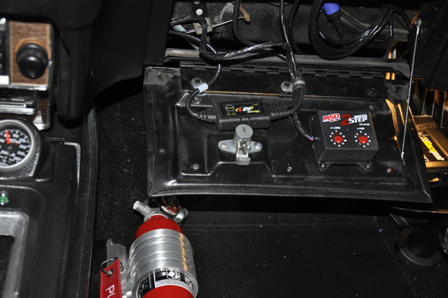
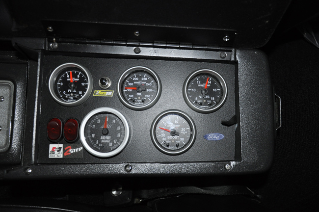
I removed the glove box tray and attached the Air Fuel controller and the 2-step for easy access. Also inside this area is where all of the sensor modules (VNet) come together before going to the Racepak unit.
When data logging in telemetry mode (real time), real time data is logged on the laptop and you can collect a good 15 min of data. I found it helpful to display the graphs of some parameters, such as vacuum, or AF as I drive down the highway and see how things respond to the accelerator pedal while under normal load. To just log data at the track, I installed a record button in the console that you push to start the record session giving a 3 minute interval which is enough to capture the burnout, staging, and actual run.
The things that I am currently logging include: Engine RPM, Driveshaft RPM, as well as engine to driveshaft ratio, Acceleration G's, Lateral G's, Manifold vac, Fuel Pressure, Oil Pressure, Air/Fuel ratio, Voltage. I also monitor the clutch switch so I can see when the clutch is depressed, and for hoe long. I also have the ability to see clutch slip. With all of this data, I can really see how things are responding, and between the Accelerometer G meter and DS RPM, can see tire slip, and with the Lateral G meter, tire hop. There are many more sensors that can be added over time.